The Telematico NMS3000
It’s been a while. This time, I’m continuing the “computers that I never had” series to talk about a project that has been sitting on my bench for literally months, waiting for a little less busy times to complete: the Philips Telematico NMS3000.
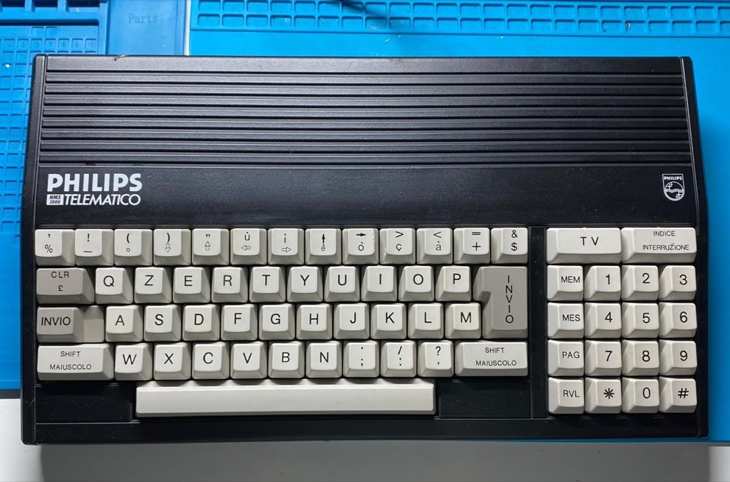 The Philips Telematico NMS3000
There are a couple of reasons why I bought this relic to work on: it takes me right back to the pre-Internet days of modems, X.25, and Videotex; it’s simple enough that I actually stand a chance of fully understanding how it works; and it has near-zero information available on the Internet. That last part forces me to discover things on my own, which, if you’re the rabbit hole type, you know is the best part.
What is Videotex
For the uninitiated, Videotex followed the Teletext standard found on TVs in the early 70s and was an early, pre-Internet, two-way electronic communication system enabling users to communicate and interact with information services via standard telephone lines and a terminal with a modem, displaying text and rudimentary graphics on a screen. Videotex, like Gopher was a precursor of the Internet.
A lot of European countries had their own thriving Videotex services. France had the famous Minitel, and here in Portugal, we had a service provided by the now decease Telepac. We could access Videotex via a standard dial-up line or an X.25 packet-switched connection, provided we had the necessary NUA (Network User Address) credentials. The coolest part about our local service was that it provided a bridge to international services—meaning we could jump to the French Minitel network.
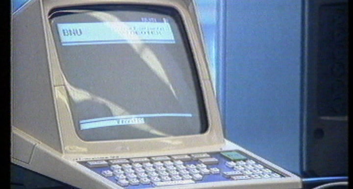 A Portuguese bank announcing their Videotex service (video)
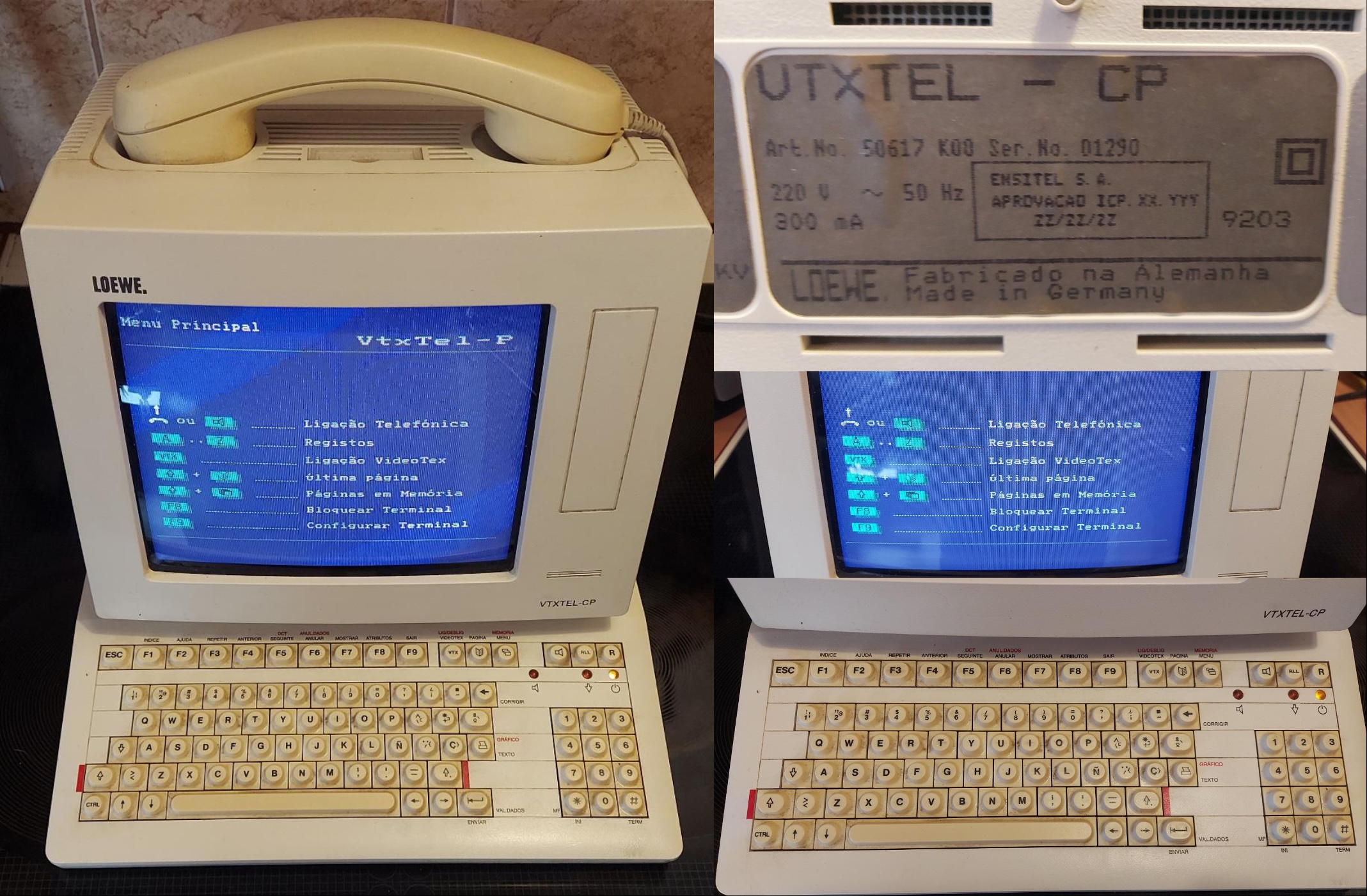 The Loewe VTXTEL-CP terminal used in Portugal
I vividly remember (ab)using my university’s X.25 connection in the pre-Internet days to access Minitel, specifically to get onto QSD, a somewhat popular hacker chatroom service. But those are stories for another day.
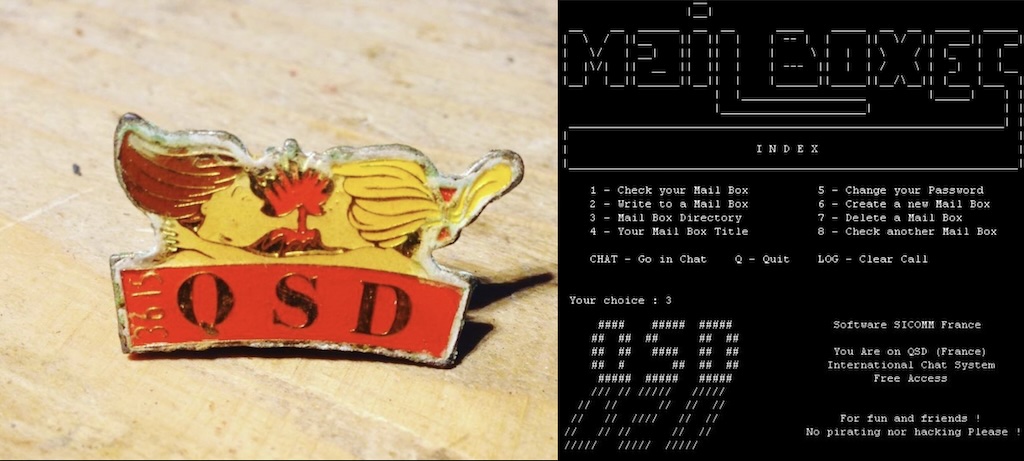 QSD Chat
And yes, it’s Videotex, not Videotext.
What is the Telematico
The Telematico is a dedicated Videotex terminal launched in 1988, specifically tailored for the Italian market to access their Videotel service.
Under the hood, this terminal features:
- A Z80 CPU clocked at a “blazing” 3MHz
- 32K of ROM and 4K of RAM
- A 256-byte EEPROM to save user configurations
- A CEPT Videotex Level 1 video decoder
- A built-in CCITT V.21 and V.23 (1200/75 baud) capable modem
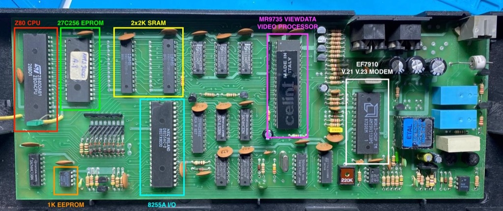 Telematico PCB
Architecture-wise, the Telematico is loosely based on the MSX1 standard—a platform Philips knew inside and out because they manufactured plenty of MSX computers themselves. But it’s not really a MSX. The ICs on the board are standard fare for late-80s hardware, with one massive exception: a mysterious, proprietary 40-pin chip labeled “Celint” that handles Videotex decoding and video generation. More on that in a bit.
Alright, let’s turn this thing on.
How do I even power this up?
Like I mentioned, documentation for this terminal is virtually nonexistent online. I couldn’t find a user manual, let alone schematics, and the unit arrived bare-bones—no cables, no power supply. Luckily, I stumbled onto a single webpage that included this connector diagram:
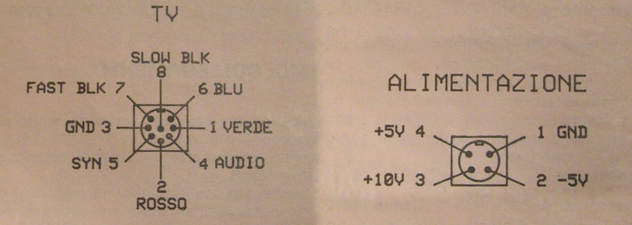 Video and Power connectors
Well, it’s a start. These are standard 8-pin and 4-pin DIN connectors, which means I can actually build my own cables.
For power, I decided to use a DC-DC PicoPSU-150-XT ATX power supply mated to a screw-terminal adapter. Standard ATX power supplies don’t output a 10V line, so I put two diodes in series to drop the 12V rail down to roughly 10.6V, which hopefully is within tolerance for the terminal.
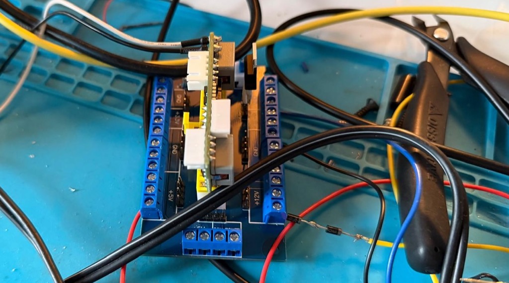 PicoPSU power supply for 5V, -5V and 12V converted to 10V
As for video, the Telematico outputs RGB + sync. This works beautifully with my Retro Scaler 2x to upscale and convert the analog signal to clean HDMI for modern monitors.
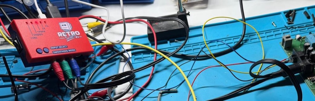 Retro Scaler 2x connected to the Telematico
One last hurdle before flip-the-switch time: the way that the keyboard is connected to the mainboard leaves almost zero maneuvering space if you want to probe components while the machine is running. To fix this, I hacked together a quick extension harness using a mess of jumper wires and blue tape.
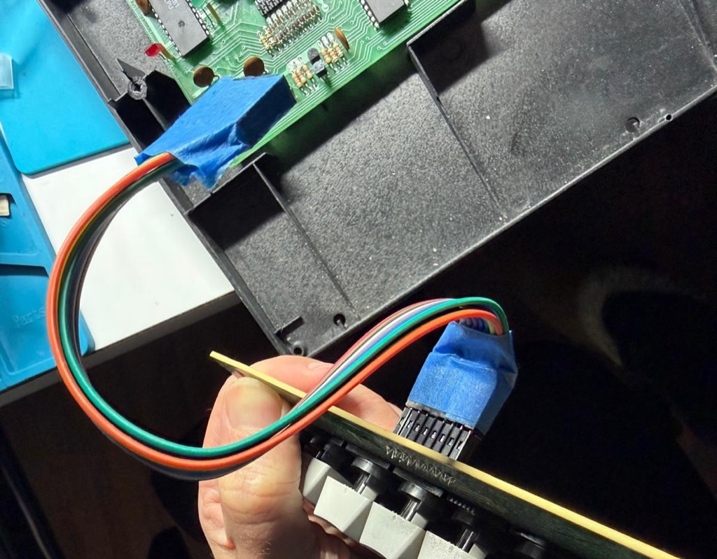 DYI keyboard extension
I think we’re ready now.
 I turn the Telematico on for the first time
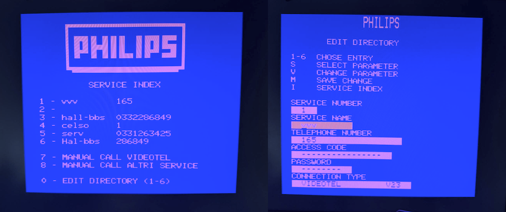
I flipped the switch. The classic Philips logo materialized on the screen, followed immediately by the dialup phonebook and configuration menus in Italian. Success.
Bringing the Telematico online
The next logical step is connecting the terminal to another computer. This sounds simple on paper, but it obviously never is. There is no serial port, no parallel port, and no expansion bus. The only way data leaves this machine is through its modem and a telephone line.
So, the plan was simple: link the Telematico’s internal modem directly to a cheap StarTech USB hardware modem hooked up to my Mac. Easy, right?
Wrong.
You can’t just wire two old modems together with a phone cord and expect them to talk. Modems expect to see a real, live telephone line. Specifically, they require a direct current (usually around 24V to 48V DC) passing through the line to physically energize the subscriber loop. This is how the modem senses that it is “off-hook” and activates its internal data circuitry. Without that voltage, the modem assumes the line is dead and refuses to play along.
To trick both devices, I built a simple line voltage injector circuit using an external power supply to simulate that off-hook voltage:
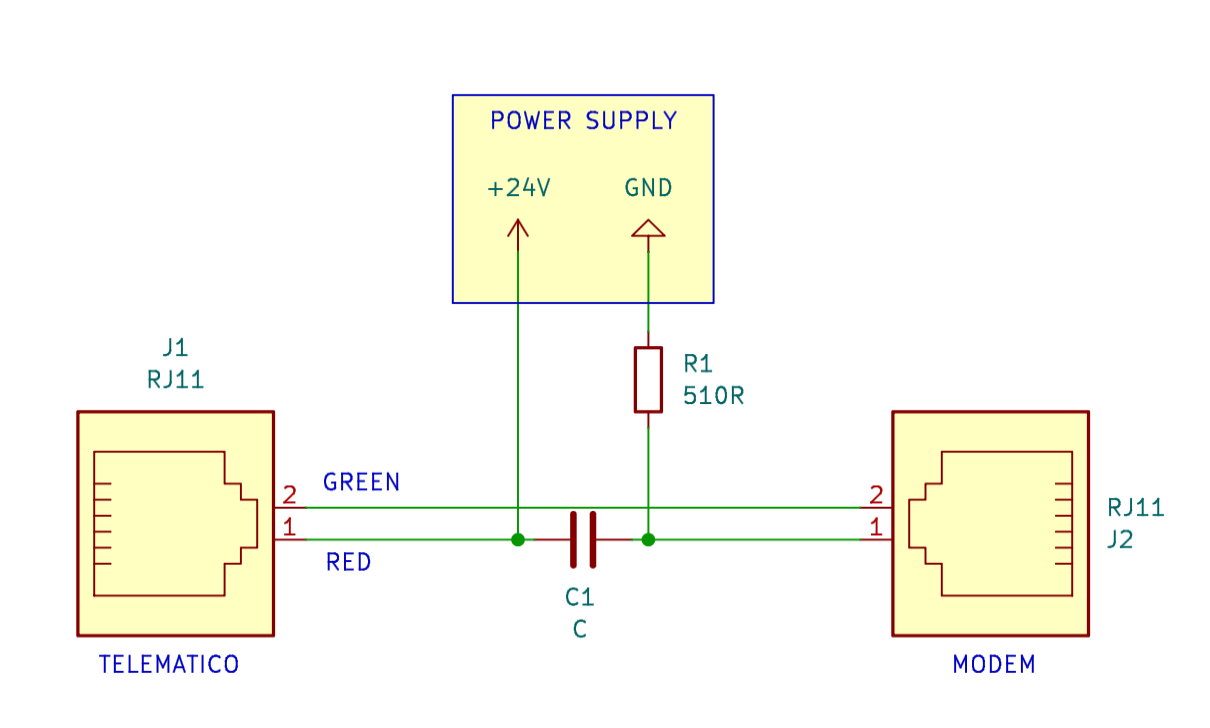 Injecting 24V to simulate the off-hook voltage of a telephone line
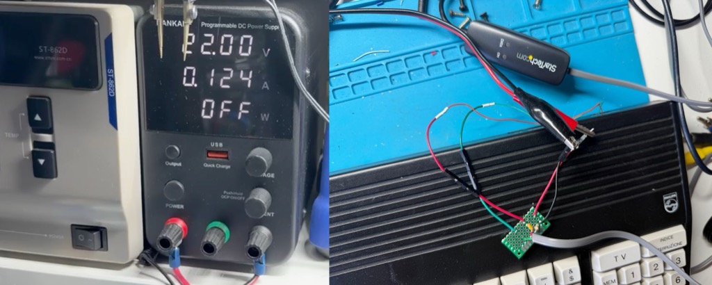 The circuit above in a small PCB
Next, I created a phonebook entry on the Telematico that simply dials “1” (the actual digits don’t matter; I just need the software to trigger the hardware relay to go off-hook) and set the connection type to Videotel and V.23 (1200/75 baud).
Time to test. I fired up minicom on my Mac, configured the serial port to 115200 bps 8N1, enabled local echo, and issued the manual answer command (ATA). Simultaneously, I told the Telematico to dial. I hear the relay dialing the number “1” and the modems handshaking. A few seconds later CONNECT shows on the screen.
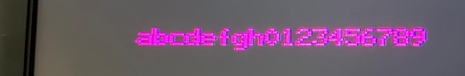
I typed a test string into minicom to see it echo on the Telematico’s display. But instead of abcdefgh0123456789, the terminal printed a garbled mess where some characters are right but others are not.
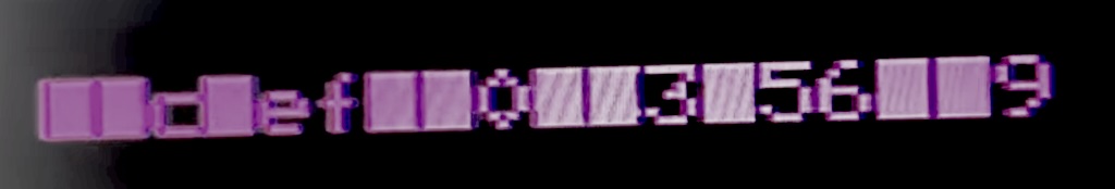 Definetly not abcdefgh0123456789
This is surely a parity mismatch, I thought. The standard back then for Videotex and Minitel systems was 7E1 (7 data bits, Even parity, 1 stop bit), not the modern 8N1. I reconfigured the Mac to 7E1. Same garbled mess. I tried two stop bits, odd parity, no parity—every conceivable combination left the text unreadable.
Maybe it was my USB modem settings? I spent hours fiddling with ATS registers, but it made no sense because the modems were already successfully locked onto a carrier. I tried abandoning minicom entirely, writing raw Tcl send/expect scripts and manipulating stty flags directly. Nothing worked.
Defeated by software, I pulled out the oscilloscope and started probing the digital data lines directly on the Telematico’s PCB while sending characters from the Mac.
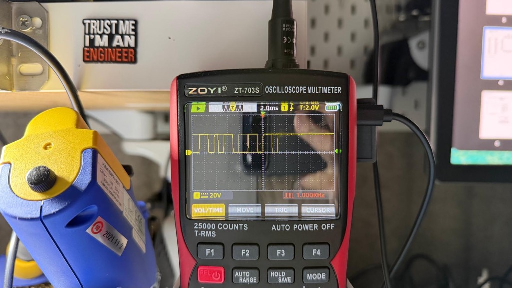 Probing data lines inside the Telematico
This impasse dragged on for week(end)s. Poking around a board blindly without a schematic isn’t great.
I learned KiCad
I decided to use this roadblock to cross off an old item from my to-do list: learn KiCad, the open-source PCB design suite and while at it, reverse-engineer the Telematico and create its schematics.
I won’t lie—this took an immense amount of time. It involved countless hours of continuity testing, tracing PCB traces, and plenty of trial and error. But it was loads of fun too. KiCad is a joy to use once you push past the initial learning curve, and the community resources online are awesome, I even got help from one of the devs on Bsky.
So yes, now the Philips Telematico NMS3000 finally has schematics. If you want to explore them, the complete KiCad sources are here, and I’ve also hosted an interactive HTML version for easy browsing.
Now I know how things work and I know what to probe.
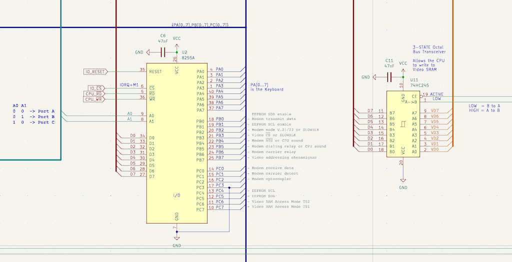 Intel 8255 I/O chip
Here are the EF9810 FSK Modem chip connections.
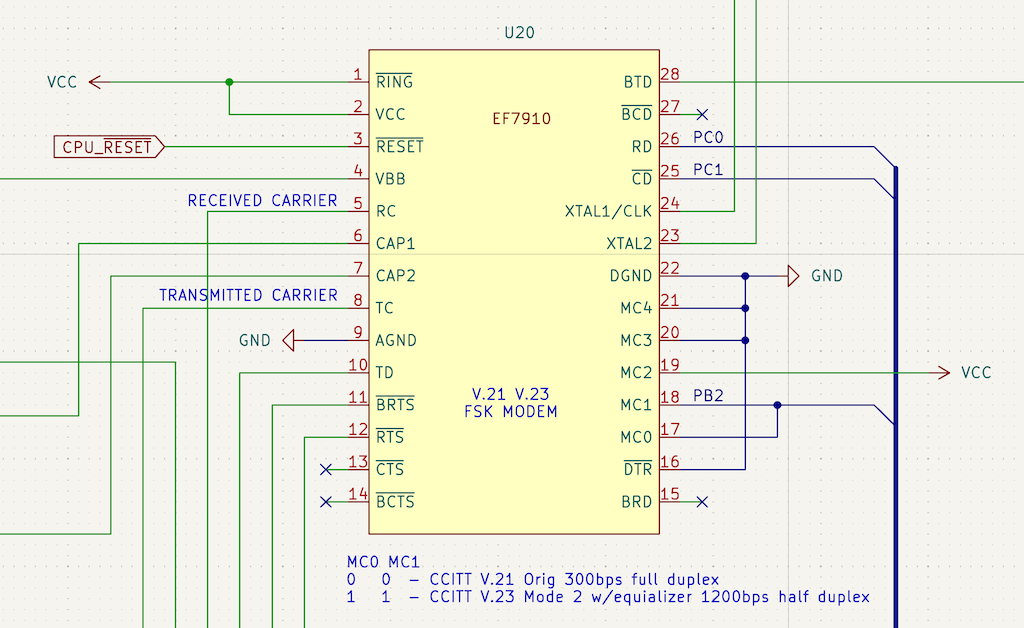 EF9810 Modem
One of the nice side effects of reverse engineering the machine is that now I can deduce the system’s entire memory map just by looking at how the address lines interact with the line decoders and the I/O chip, all without having to read a single line of the ROM code.
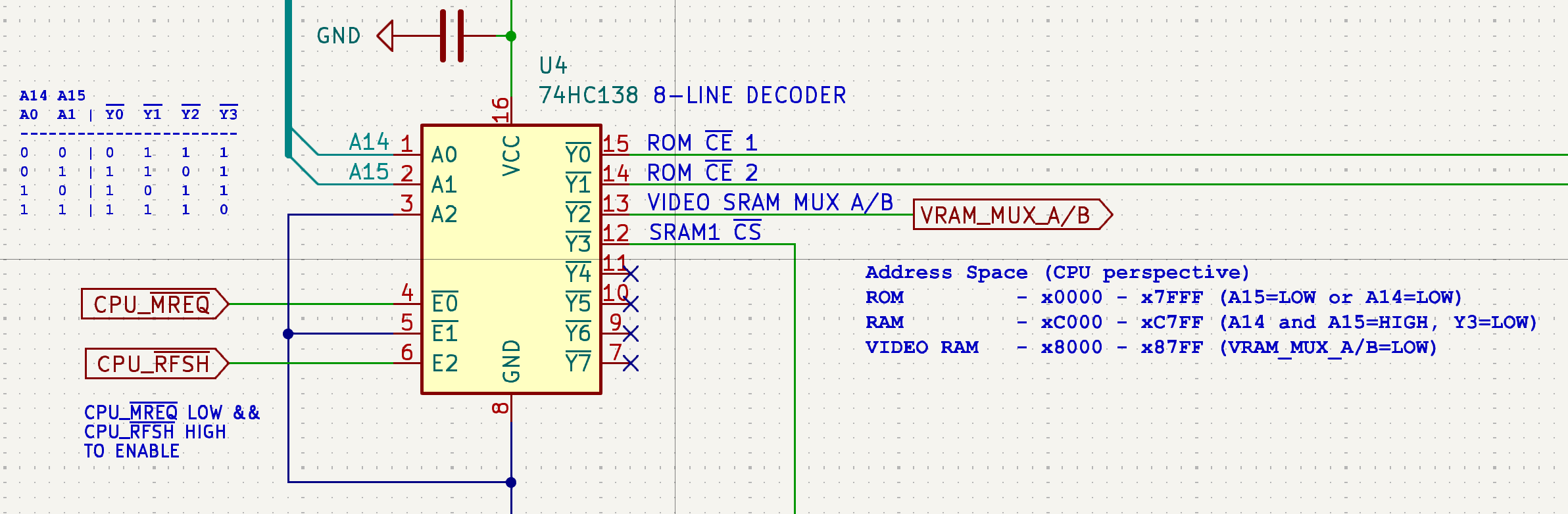 This 8-line decoders tells us how the memory map is organized
Parity conundrum, solved
Armed with the new schematics, I hooked up the scope again and tracked a single character’s data stream all the way from the input pins of the modem chip to the data pins of the 8255 I/O controller. Here’s what I discovered.
When sending the lowercase letter “a” over a true 7E1 connection, you expect to see 10 bits serially: a 0 start bit, 7 data bits (1000011 in least-significant-bit order), an even parity bit (which should be 1 to make the total number of ones even), and a 1 stop bit.
Instead, the scope showed that the parity bit arriving at the terminal was always 0, regardless of what character I sent.
The Mac was broadcasting data as if it were locked into 8N1, completely ignoring my 7E1 configurations. How is that possible?
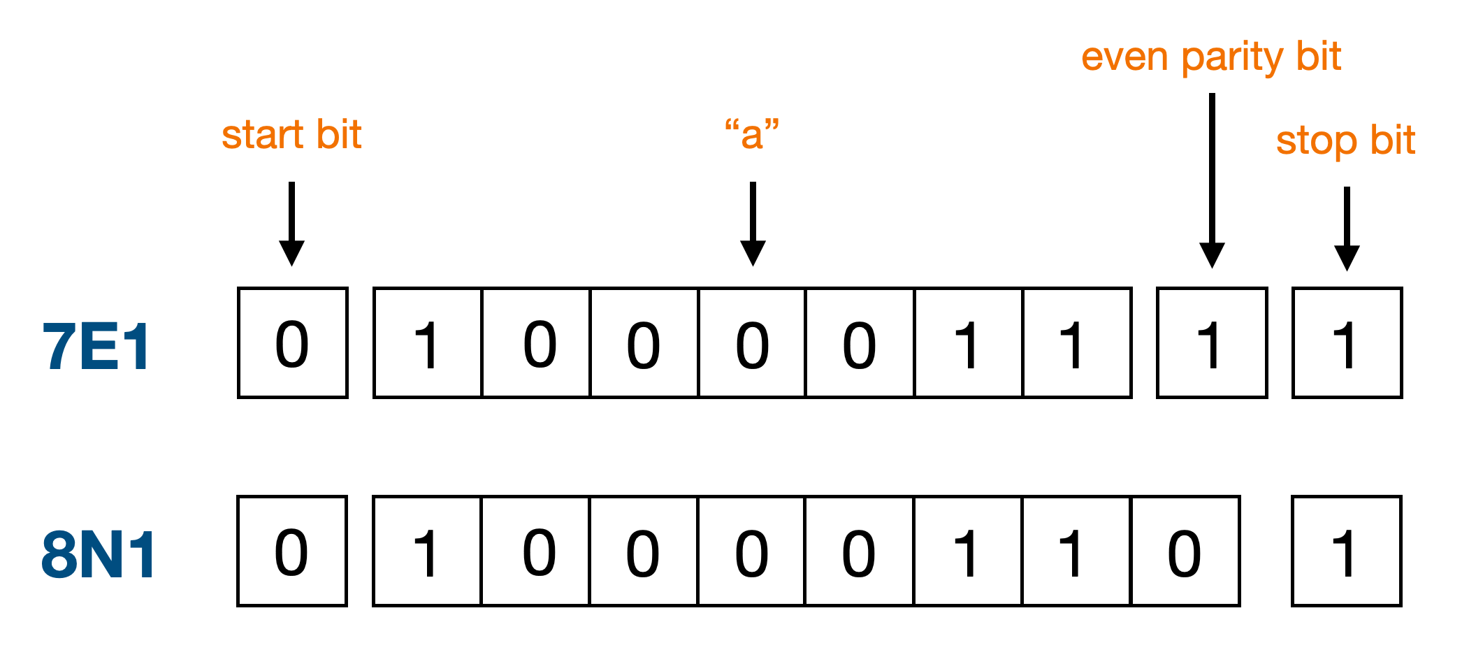 "a" in 7E1 and 8N1
As it turns out, macOS’s native AppleUSBACM serial driver has a bug: it defaults internally to 8 data bits (CS8) and completely ignores standard POSIX system calls to alter character size or inject hardware parity flags. It forces raw, 8-bit binary no-parity communication down the wire.
Had I plugged the USB modem into a Linux box or a Windows PC and it would have worked instantly. Kill me now.
Fortunately, the workaround is simple. We can calculate the parity bit in userland and pack the result into a raw 8-bit byte before sending it:
const evenParity = (b) => {
  b &= 0x7f;
  b ^= b >> 4;
  b ^= b >> 2;
  b ^= b >> 1;
  return b & 1;
}

const to7E1 = (b) => {
  const data = b & 0x7f;
  const parity = evenParity(data);
  return data | (parity << 7);
}

const encoded = Buffer.from("abcdefgh0123456789").map(to7E1);

await writeSerial(port, encoded);
No more garbled stuff.
 Yay
Yay
I have good communications with the Telematico now.
A Videotex server, powered by Cloudflare Workers
Now that I have good communication between the Mac and the Telematico, I wanted to build a Videotex server that it could dial into and interact with.
I found the datasheet of the mysterious Celint Videotex decoder in a dark corner of the Internet, it’s actually a GEC Plessey MR9735 Teletext/Viewdata 625-Line Video Generator, and it gives me enough clues to get me started:
- 24 row x 40 character display.
- Support for ASCII and the oldest CEPT Level 1 Videotex (002 character set).
- Support for Viewdata attribute encoding (colors, flashing text, graphics mode).
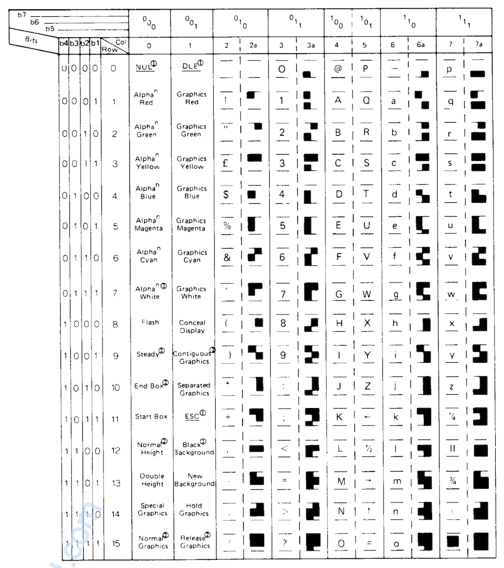 002 character set
Alright, I think I can work with this, here’s what I’m planning:
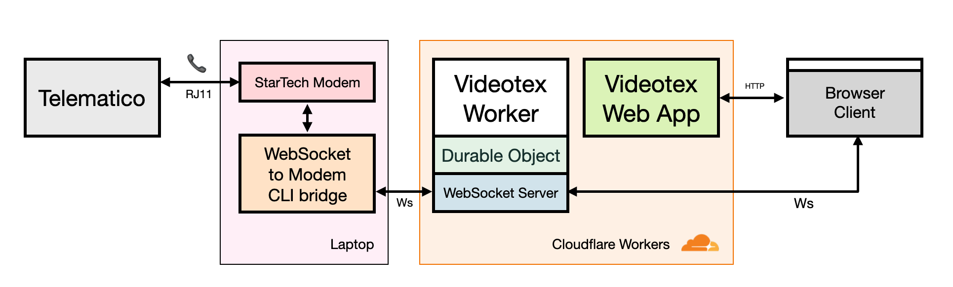 Diagram of my Cloudflare Workers powered Videotex server
I roll up my sleeves and start coding. Well, half coding and half vibe-splopping, let’s be honest.
The backend runs entirely on Cloudflare Workers using a Durable Object to manage active client sessions, state machines, and real-time WebSocket connections. The server exchanges keystrokes, raw videodata frames, and other terminal control codes.
To make testing easier, I also built a browser-based companion client using Vite+React and the open-source package @techandsoftware/teletext that renders videotex pages as SVG.
 A Videotex Web Terminal
You can actually try out the web version of the terminal at https://videotex.arkanoid.workers.dev/
The final piece of the puzzle is interfacing the server with the Telematico. For that I wrote the modem.ts script that connects to the Videotex server running on Workers over WebSocket on one side and my local RS-232 USB StarTech modem on the other. Once this proxy opens a Videotex session, it instructs the modem to answer a phone call using the “ATA” command. At the same time I manually instruct the Telematico to dial out if all goes well the connection is established.
 WebSocket to RS-232 proxy
Here’s a video of an end-to-end session simulating what would happen IRL in the late 80s when you’d dial up a Videotex service.
Playing with the ROM
The Telematico has a 27C256 32K EPROM that holds the firmware (or should I say operating system?). I wanted to see what was inside, and more importantly, change it.
First I desoldered the original chip and installed a clean IC socket so I could swap chips easily moving forward.
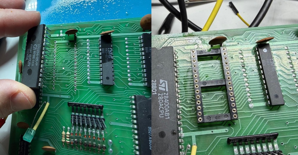 Replacing the 27C256 with an IC socket
Next up I’m going to use my Retro Chip Tester Pro to dump the EPROM. I place it in the ZIF socket, select the 27256 EPROM option and a few seconds later I have a file with its content in it. You can find the image here.
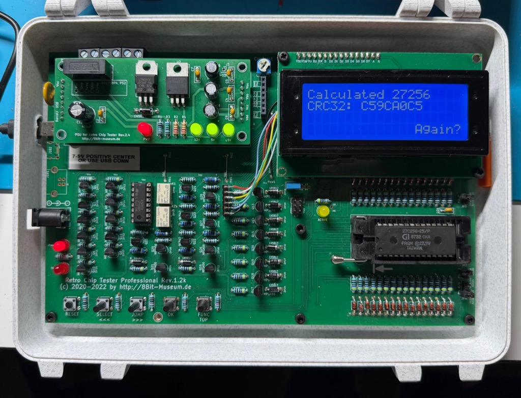 Using the Retro Chip Tester Pro to dump the ROM
Now for something fun I modified the binary image, translating the menu strings into English. But instead of burning a vintage, one-time-programmable EPROM, I opted for a modern alternative: the One ROM.
Designed by Piers Rocks, the One ROM is an incredible open-hardware project that uses a modern microcontroller to emulate classic 24-, 28-, 32-, and 40-pin legacy EPROMs.
But does it work with a Telematico? Let’s find out.
I had a few 24 and 28-pin One ROMs manufactured and shipped from PCBWay a few weeks ago.
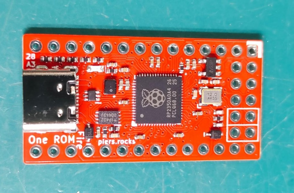 A 28-pin One ROM
So I burned my new English Telematico ROM image into the One ROM right from the browser using nothing but a USB-C cable and this Web app, and then put it in the PCB.
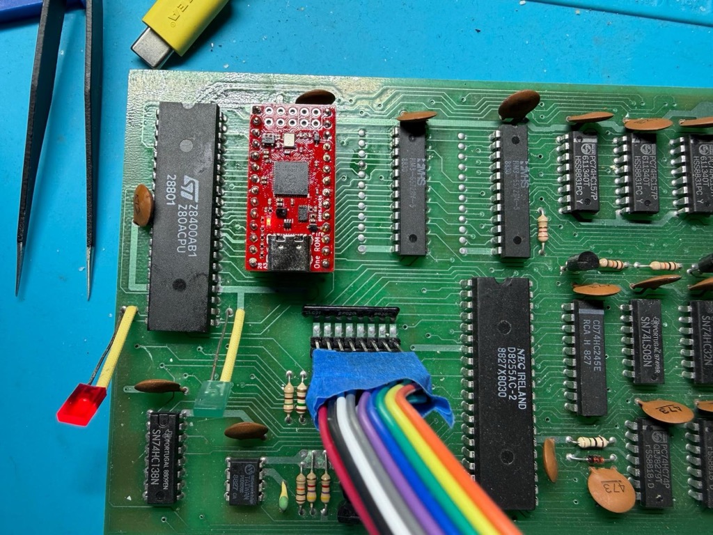 The Telematico with the One ROM replacing the 27C256 EPROM
Then I turn on the machine and surprise, not only the One ROM works perfectly but I also have the first English Telematico NMS3000 in the world.
 The Telematico with the One ROM replacing the 27C256 EPROM
Here’s the english version of the ROM.
Final words and ideas
That’s a wrap. You can find the KiCad schematics, the Videotex server and utilities, the ROM dumps and the IC datasheets in my NMS3000 GitHub repo.
I’m going to give the terminal a well-deserved rest on the shelf for now, but I have future ideas:
- A USB keyboard adapter
- An RS-232 hardware bypass: Adding a physical serial port directly to the UART lines to bypass the internal modem entirely.
- Writing a native game and burning it in ROM: It’s a pure Z80 system with RAM and (now) documented I/O maps. Writing a custom bare-metal game sounds like possible.
Hope you enjoyed this one.