Building a Frankenstein 64
Last year, I decided that I was going to build a Commodore 64 from scratch. This is the blog documenting the project.
It’s no secret that I love fiddling with retro computers, especially those I owned when I was a kid. When I revisit ancient technologies and hardware that were part of my younger years, I’m overwhelmed with that warm nostalgia feeling. But it’s not only that. Understanding how old computers work is also educational and helps me look at the modern world with a wiser perspective.
The C64 was a big part of my youth. On one 80s summer, during the school holidays, I worked hard on a job and accumulated some money. My parents helped with the remaining, and I finally bought the classic breadbin C64, a Datasette, and an LX-80 Epson printer. It was a significant upgrade over the Timex Sinclar 1000 and ZX Spectrum 48K I owned before. Day and night. It was fast, had gorgeous graphics and sprites, stunning sound, and two joystick ports. I remember thinking that the games were out of this world.
Because its design was so clever and powerful for an affordable 8-bit home computer, it quickly became the most-sold computer in the world (Guinness record here). Almost 40 years later, there is still a massive community of retro-computing hobbyists doing all sorts of things with C64s: writing software, building new peripherals and accessories, reverse engineering MOS’s custom chips and creating modern alternatives, selling replacement PCBs or plastic cases from the old injection molds, you name it.
As for me, I wanted to build a Commodore 64 replica from scratch.
The requirements for this project were:
- Build a C64 to last. I wanted to use as many new components as possible, like transistors, resistors, inductors, capacitors, voltage regulators, connectors, and other parts.
- Make it easier to repair or modify in the future, using ICs sockets everywhere, for example.
- Replace some of the custom MOS chips with reverse-engineered modern alternatives for fun.
- Pimp up the final product, and make it beautiful and collectible.
A new PCB
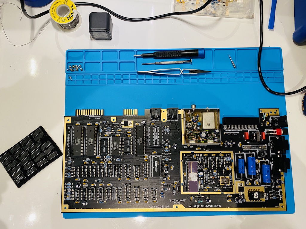
I first bought a brand new beautiful SixtyClone replica PCB in Bob’s Bits Tindie shop. The C64s went through a few PCB revisions making them more reliable and cheaper to produce over time. I ended up choosing the first, most famous one: the Assy 250407 Rev. C. Black soldermask because it’s just gorgeous.
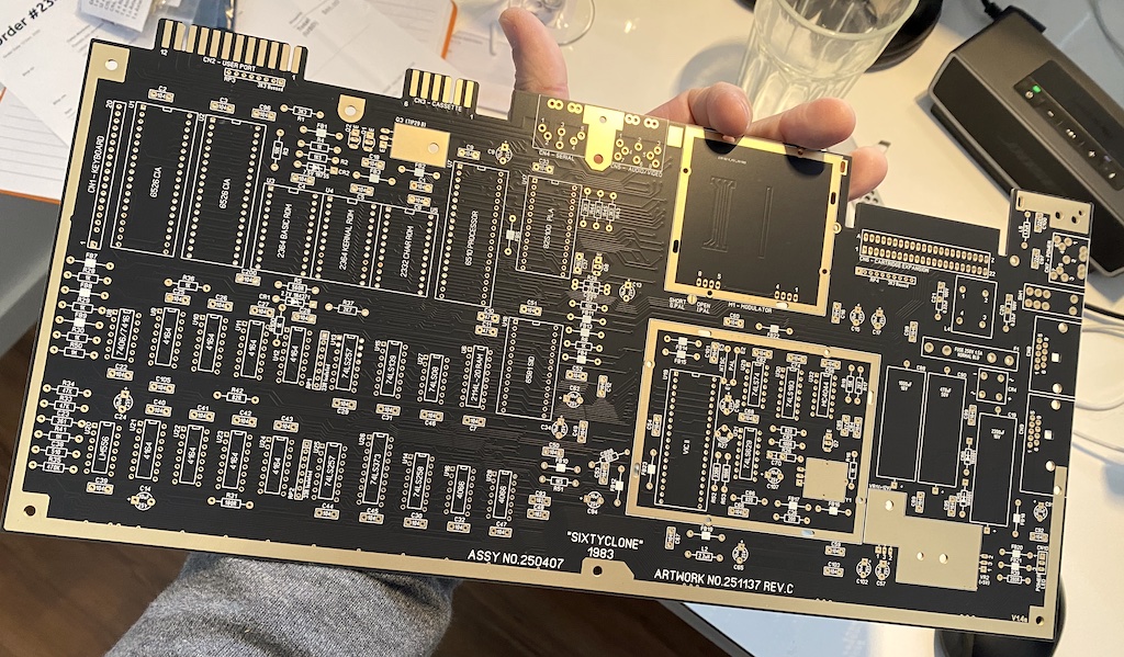
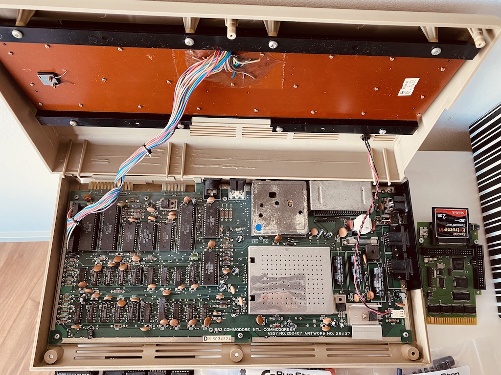
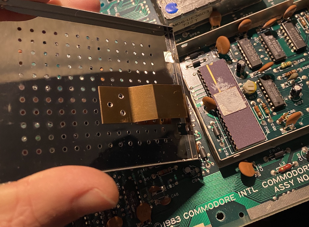
Look how it compares with the same PCB on my other original, still working, C64.
The C64 chips
I’m calling this project the Frankenstein 64 because I will use a mix of old MOS chips and brand-new replacements where I feel they’re appropriate. The goal is to find a good balance between keeping it faithful to the original and improving it and building it to last.
Of course, not all chips have modern replacements (subject to change, depending on when you read this). I will use some original chips salvaged from my own non-working original C64 PCBs and others bought online.
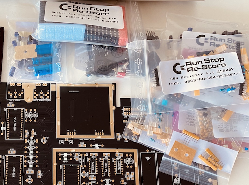
After some research, I ended up buying the “Commodore 64 parts kit” from the Reotro8BITshop store online. The kit includes new resistors, capacitors, passive semiconductors, board connectors, common logic chips, and good-quality IC sockets. It answers most of my requirements, has good reviews, and mentions the SixtyClone boards in the description. The full BOM list can be found here.
Retro8BITshop also has all the MOS chips and others you need if you don’t have them in your stash. Another good place to find good deals on old C64 chips is eBay, but make sure to choose sellers with good reputation scores though; it’s not uncommon to get chips that weren’t tested and are faulty.
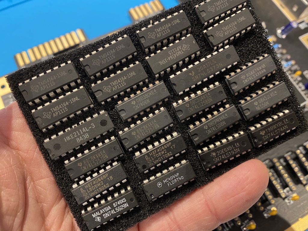
Old chips
Some chips are regular 74(LS) TTL logic that you can buy brand new, but the others aren’t manufactured anymore. Here’s the list of the original old chips I will be using:
- Two MOS 6526, aka the Complex Interface Adapter chips. The CIAs serve as the I/O port controllers. They do parallel, serial, and interval timers and have an integrated “Time Of Day” clock with alarms that almost no software uses. Things like the user ports, disk drives, joysticks, keyboard scanning, and even the blinking cursor depend on the CIAs. The 6526 is a unique chip, but as I write, there is a modern FPGA-based replacement in the beta testing phase, but I didn’t consider it.
Fun fact: the Commodore Amigas would later use the improved MOS 8520/8521 chips, which are drop-in compatible with the 6526 (with a few subtle differences).

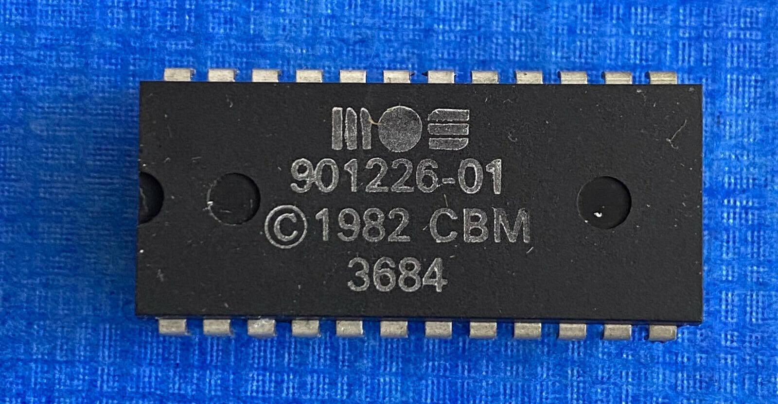
- Three ROMs. Two MOS 2364 ROMs for the Basic interpreter and the Kernal, and one MOS 2332 ROM for the Character Set. These chips can easily be replaced with EPROMS burned with the same ROM dumps. More on this later in this blog.
- The MOS 6510 microprocessor, aka the C64 CPU. A successor to the wildly successful 6502 chip used in the PET, VIC20, 8-bit Ataris, Apple II, and even the BBC Micro (you have to check out this website if you want to learn more about the fascinating story of the 6502).
Fun fact: believe it or not, there are 6502 variants still being manufactured today, but the 6510 is not. However, some adaptors can take a 6502 compatible chip and add the 6510 extra functions using discrete logic. See the MOS CPU replacer. And, of course, someone is working on an FPGA-based replacement, but it’s not quite there yet.

- The MOS 6569, aka the Video Interface Chip II. The VIC-II is the graphics chip of the C64, which was revolutionary at the time (some will say that it played a big part in the C64 huge success.) This chip generates the video signals and can do character graphics, bitmaps, sprites, smooth scrolling, raster interrupts, and other tricks that make the C64 games look and feel vastly superior to the ones from other 8-bit systems. There are PAL and NTSC variants. Again, after many years of development, there is now an FPGA-based replacement (github), but it’s still new, buggy, and expensive, and I didn’t consider it.

-
Eight 4164 DRAM chips. Each chip has 65,536 words of one bit. RAM chips are often the source of C64 malfunctions, so you must ensure they’ve been tested and have a few spares around, just in case. SaRuMan-64 is relatively a cheap, modern static RAM replacement for these chips, but it only works with the 250466 and 250469 PCBs that have 64k x 4 bits DRAMs, so I didn’t consider it.
-
One Motorola MC4044 chip, a phase-frequency detector used on the Assy 250407 PCB clock circuit. We will talk a lot more about the clock circuit later.
Modern alternatives
Now let’s look at the chips that I replaced with modern alternatives.
PLA
The first one is the 906114-01 Programmable Logic Array (PLA), a hardware programmable chip that does combinatorial logic. The PLA is responsible for doing “bank switching” on the C64, a critical part of its architecture. Between the standard 64KB RAM, ROMs (Basic, Kernal, Characters = ~20KB), color RAM, and other RAM or ROM coming from expansion ports, the C64 has much more addressable memory than the 6510 CPU can handle (the 6510 has 16 address lines = 2^16 = 65536 bytes.) To allow the CPU to access all this memory, the PLA has “latches” that the CPU can use to connect or disconnect the different memory systems to the 16-bit address bus.
PLAs are very sensitive and one of the first chips to go when things age and fail. Fortunately, Thomas ’skoe’ Giesel literally dissected the C64 PLA and reverse-engineered it in 2012 and opened doors to a few modern drop-in alternatives that you can use. I chose the PLA20V8, which uses two programmable logic chips from Lattice Semiconductor, also known as GAL chips. You can either build your own or buy one pre-assembled on eBay.
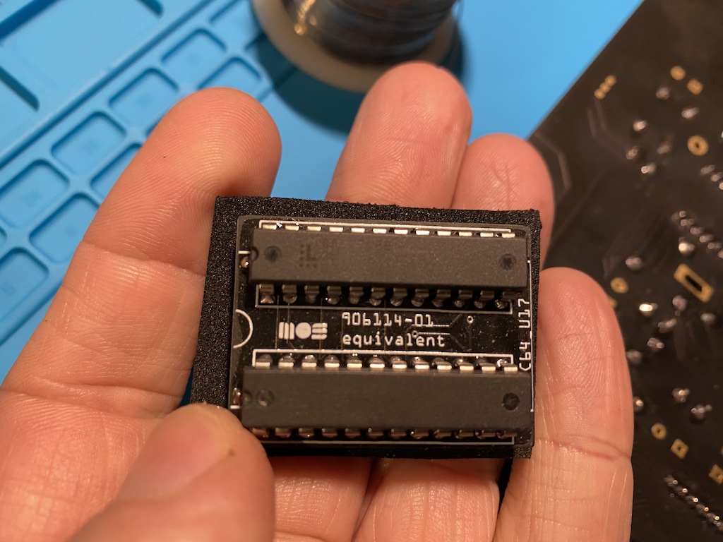
Other fancier alternatives are the PLAnkton, the neatPLA, or the J-PLA.
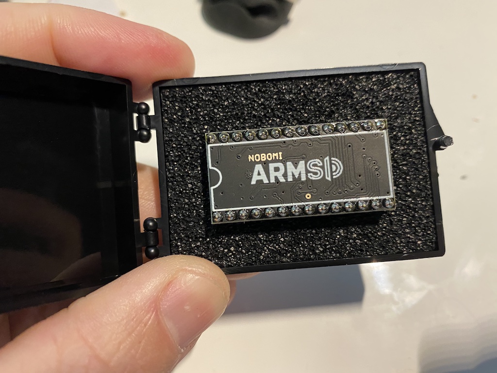
SID
The MOS 6581 Sound Interface Device. The SID is a hybrid chip containing both analog and digital circuitry. It features three independent voices which can be programmed using different waveforms and had multiple revisions over time; they say that no two SID chips sound the same.
Like the VIC II, this chip was also ahead of its time and played a significant role in the C64 success. It helped popularize the chiptune culture and kickstarted a global community of musicians and listeners that still exists today.
Due to its analog nature the SID is very failure-prone, hence rare, hence expensive. So rare that a lot of eBay sellers have the SID chips removed the C64s and sell them separately for maximum profit.
It isn’t easy to emulate the perfect SID sound in software, but the chip is so popular even today, and there’s been so much research around it that there are a few good modern alternatives worth exploring today.
One of the best, most faithful options is the ARMSID. It has an ARM Cortex M4 processor and flash memory and can be configured or upgraded with newer firmware versions using software tools provided by the author.
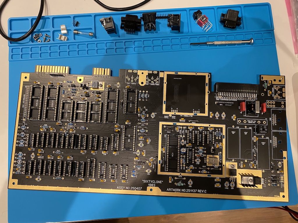
Assembling the SixtyClone
Alright, I have everything I need to make this happen. It’s time to turn my Hakko soldering station on and start populating the PCB. Soldering is one of the most relaxing and satisfying parts of any electronics project for me; I love doing it.
A great resource to keep open on a browser tab while assembling your board is the C64 PCB locator; you can use it to choose your board revision, select any component and make it blink, and find where and how it fits in the PCB.
There is some science as to how to populate a PCB. The rule of thumb says you should start with the short components first and leave the tallest to last so that the PCB stays flat and unobstructed for as long as possible.
I will use high-quality gold-plated round pin sockets for all the integrated circuits. Let’s start with them.
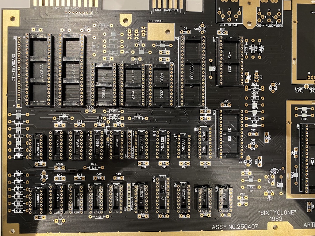
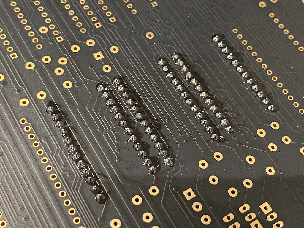
Not so bad eh?
Let’s move to the resistors, capacitors, crystal, regulators, diodes, transistors and some connectors next.
I have a few VIC II chips with different revisions lying around on various boards that I can use, but I think I will choose the oldest, most genuine, and most beautiful one: the 6569R1 in the ceramic package. Clearly a form-over-function kind of decision that I will probably regret of. The R1 has the looks, but later revisions of the VIC II are improved. For instance, the R1 only has five luminance levels.
Finally, let’s populate the big electrolytic capacitors, the rest of the connectors, and an RF modulator from an old board (I will replace this later) and squeeze all the ICs into their sockets.
Powering it on?
Before turning the board on, I need two things.
The power supply
Oddly, the C64 needs two inputs:
- The 5V DC rectified and regulated to power the most chips directly.
- The 9V AC.
Why AC, you ask? The 9V AC line generates the baseline 50Hz (PAL) or 60Hz (NTSC) signal for the CIA TOD clock (which almost no software uses) and is then rectified and regulated on the PCB internally to generate 12V DC to power the SID chip.
Funny enough, if you don’t need the TOD function or sound (the C64 boots and works fine without the SID chip), the C64 can actually be powered up with 5V DC alone.
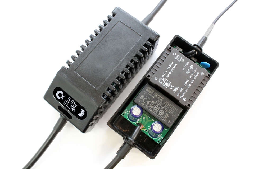
The original power brick is bulky, inefficient by today’s standards, and occasionally catches fire. In fact, they were affectionately known as the “The Commodore Brick of Death.” Luckily, there are open-hardware alternatives.
I ended up buying a modern alternative from eBay that works just fine.
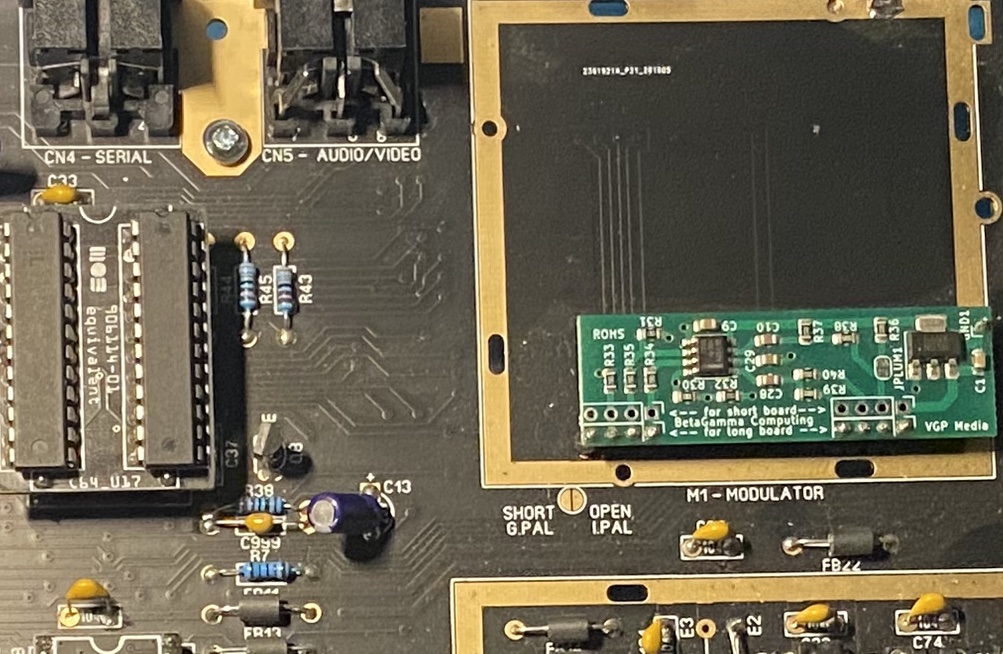
The modulator
The modulator in the C64 amplifies the luminance and chrominance signals from the VIC II and outputs RF, composite and S-Video signals.
I started this project by retrofitting an original modulator from another board. Still, its quality was terrible, so fast forward to a few weeks later, after a few bumps on the road I will describe next, I did another upgrade and replaced it with a “C64/C128 S-Video Bypass/RF kit.” There are other options.
The monitor
The perfect monitor for the C64, Amigas, and other retro-computers with S-Video/RGB outputs, is, undisputably, the Commodore 1084S (S is for the stereo version). It supports composite, S-Video, RGB, and stereo sound; you can adjust the screen position and height/width, and it’s just perfect. I have an old 1084S myself.
First attempt
I think we’re ready now. I connected the power supply and the cables to use S-Video with the 1084S and powered on the Frankenstein 64 for the first time.
The good news: it didn’t blow up, nothing smells funny, and the little red power LED is on. I put my hands on the chips; they’re all getting warm but not alarmingly hot. This thing might actually be working.
The bad news: the 1084 isn’t showing the signature C64 BASIC boot screen as it should. Or at least it can’t pick up and synchronize the video signal.
The video is out-of-sync for some reason, but I think I can see the boot sequence and the blinking cursor in there if I try hard. This tells me that the important stuff, power, CPU, RAM, ROMs, PLA, and CIAs, are all working, and that’s a big win for me already.
Ok, this isn’t so bad.
What I immediately think might be faulty is either the VIC II chip or something in the clock circuit. I replaced the VIC II chip with another one I tested on a working C64 breadbin.
It wasn’t it.
It’s definetely something in the clock circuit.
The clock circuit
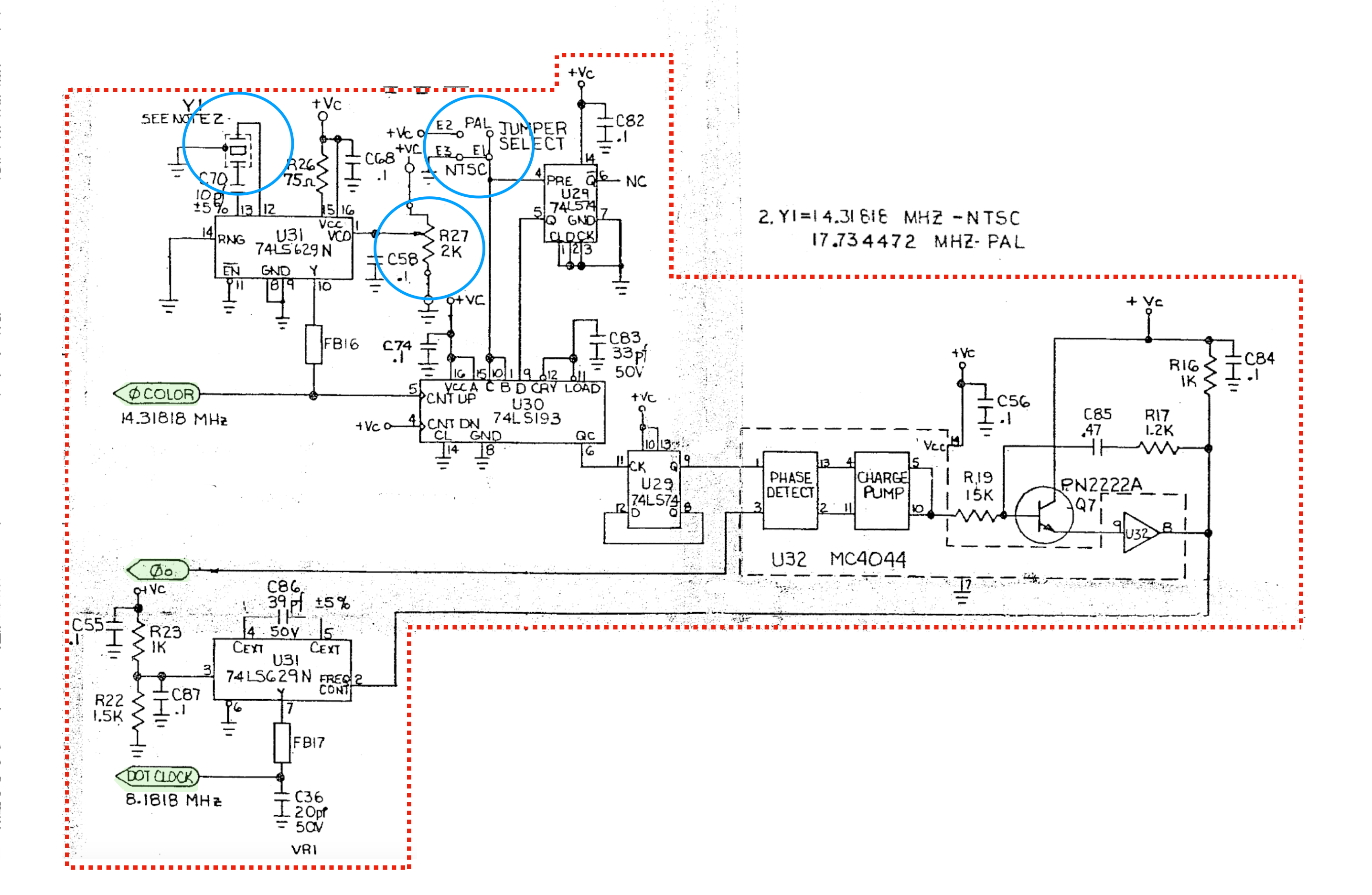
The C64 clock circuit creates the color clock from the Y1 crystal oscillator needed for the video color bursts (PAL: 17.734475MHz, NTSC: 14.31818MHz) and then multiplies it by four and divides it by either 9 (PAL) or 7 (NTSC) to create the dot clock (PAL: 7.882MHz, NTSC: 8.1818MHz). The VIC II operates at the dot clock speed and then divides it by eight to feed the 6510 CPU (PAL: 7881984 Hz, 8181816 Hz).
This page provides more details if you’re interested.
This circuit has a variable resistor R27 that allows fine-tuning the color clock. I played with it, but no luck—still an out-of-sync video.
Then I started getting suspicious about the C86 capacitor since its value didn’t match the schematics or the same capacitor I had on other boards. I changed it a few times.
At some point, I managed to get the video synchronized and get a picture on the 1084 monitor, which made me jump off the chair in excitement, only to realize that:
- The video signal was noisy and unstable.
- The C64 was not running at normal speed, and the SID wasn’t working.
- It needed constant adjustments on the R27 pot, or the video would easily lose sync again.
That wasn’t it.
I needed to get my hands dirty and go old school.
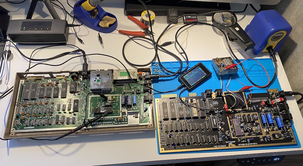
The next step was getting my DSO quad oscilloscope on and starting probing the lines in the board, trying to find anomalies and their probable source. To help with that, I used two resources:
- A good C64 running in parallel. Unfortunately, that board is a newer revision with a slightly different clock circuit, but the same principles apply.
- This page from Sven’s Techsite documented good scope readings from the C64 boards, which I could use as a reference.
Plus, my friend Luis Correia was helping me with suggestions online, which was fun.
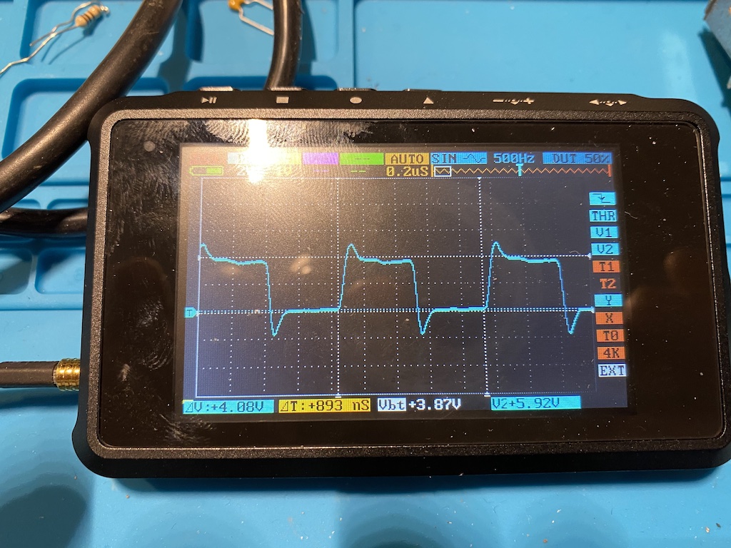
I quickly realized that my clock circuit wasn’t generating the correct frequencies or signal amplitudes, it was all messed up. But I couldn’t find why.
Next up, I started replacing everything I could: the crystal oscillator, the MC4044, the 74LS193, the 74LS629, the 74LS74, and the 2222A transistor. Still, no luck.
Frustration, big pause and eureka
I could have easily solved the issue by bypassing the clock circuit using something like this, but the stubborn in me had to find the root cause or die trying. This went on for a few days until I lost patience.
So I used another strategy that usually works for me: I shelved the project for a while and made sure I forgot about it. Putting apparently unsolvable problems to rest for some time is a great way to find solutions when you return to them with a fresh mind, without the frustration.
This pause ended up taking longer than I anticipated. I didn’t touch the PCB for months.
However, recently, I bought something that I was enamored with for a while, a Hakko FR-301 desoldering tool, which instantly made me a professional at desoldering otherwise impossible chips from old PCBs.
I took the opportunity and desoldered a few more chips from a damaged C64 board I had lying around. Some of those chips were from the clock circuit, so I thought, what if I replace the SixtyClone chips again with these?
-
I replaced the MC4044 phase-frequency detector, but nothing.
-
I replaced the 74LS629 voltage-controlled oscillator, but nothing.
-
I replaced the 74LS193 divider and BAM! I get a nice, clear, crisp picture on the monitor.
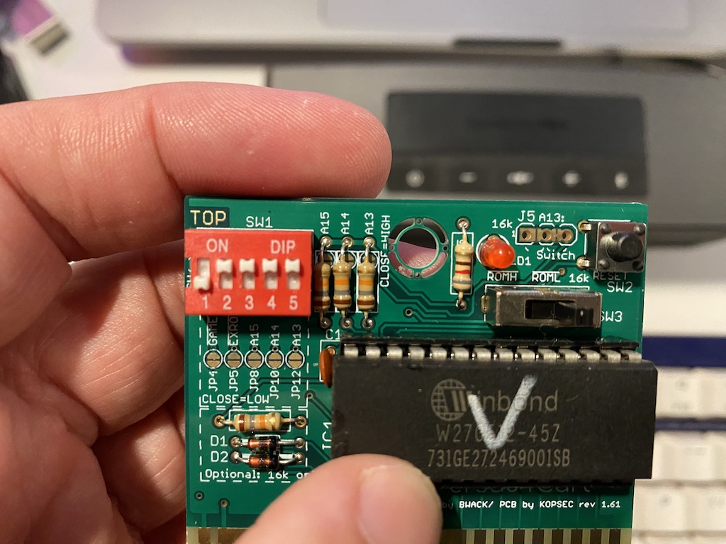
I couldn’t believe it. I plugged my Versa64Cart-based diagnostic test cartridge into the expansion port and ran the test; it gave me a 100% working C64 without issues.
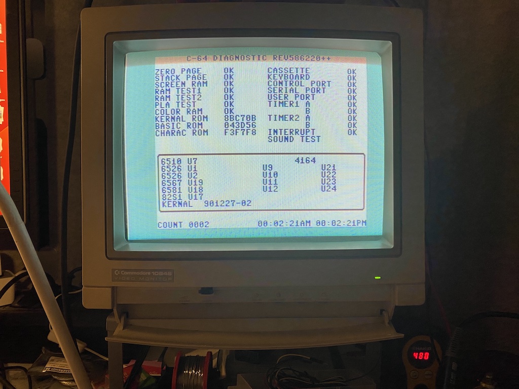
Eureka!
So, yes, it was the 74LS193 the whole time, a perfectly common TTL IC that I initially bought as new, which I can swear I had already replaced in the first round of troubleshooting.
Sigh.
Time to wrap up this project and enjoy it.
The case
Remember the “Pimp up the final product, and make it beautiful and collectible.” requirement? The case is important. Of course, the purists will say the “bread box” (aka breadbin) is the way to go because it’s the classic. I wouldn’t usually disagree, but I have other ideas.
Here’s another funny story.
In 2014, Dallas Moore was attending an auction for an injection molding company and accidentally found the lost original molds for some of the C64 models. He did a successful Kickstarter campaign and used the funds to buy the molds and produce an initial batch of new cases. Later, in 2016, Jens Schönfeld and Tommes from Individual Computers bought the molds from Dallas, brought them to Europe, and are now regularly producing new batches of cases in different colors and selling them online.
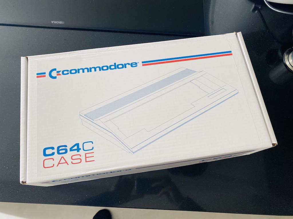
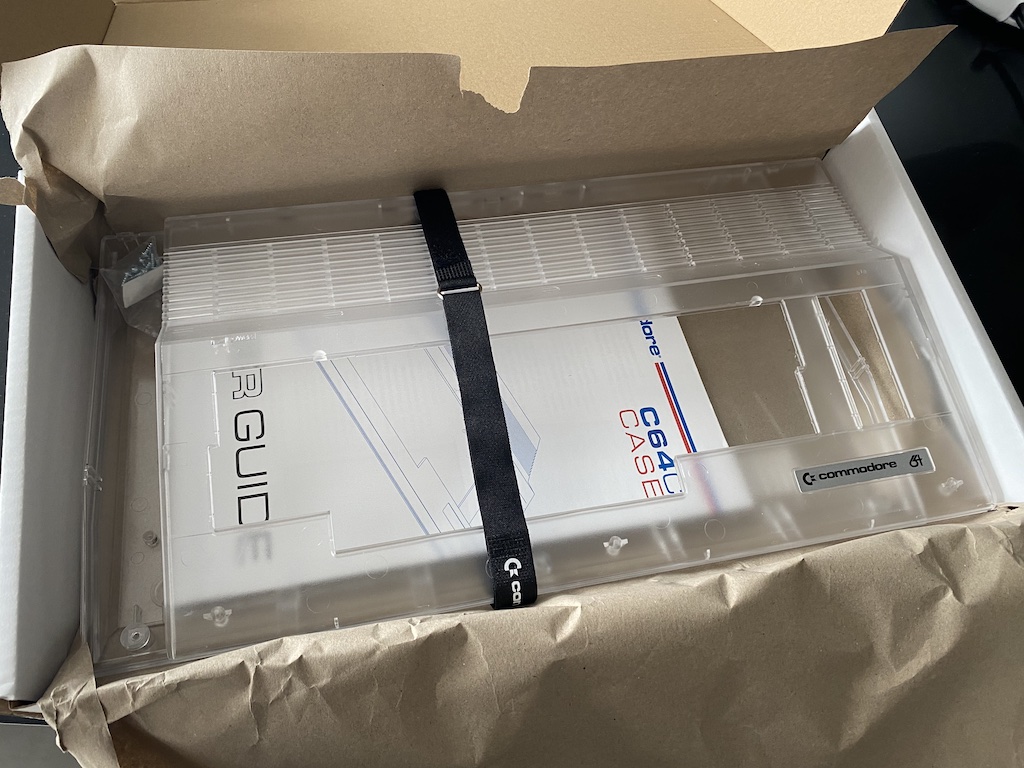
In my opinion, the coolest C64 case is the transparent version. It’s as beautiful as the original (it comes from the same molds), and it allows you the peek inside the electronics, which in themselves, are a work of art. So I bought one.
The keyboard
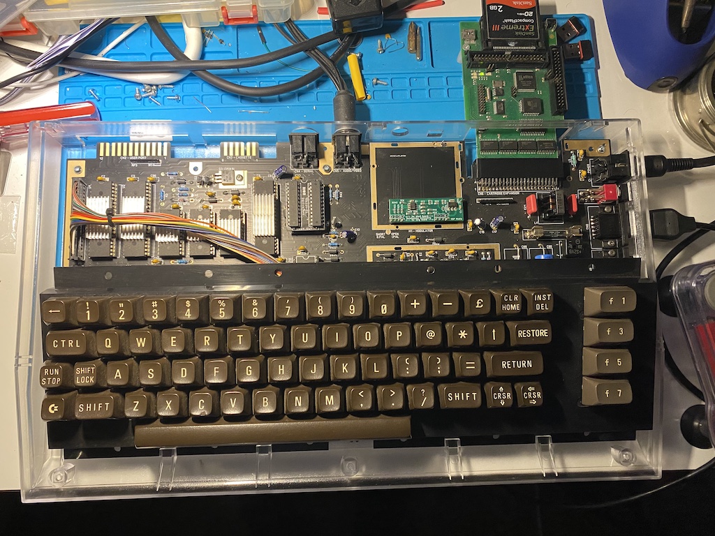
I like the original C64 keyboard; it’s iconic and robust. I have no plans to use any alternative here. I have a few that I can use, but I need to clean one first.
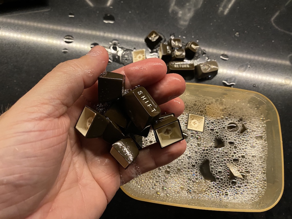
I started taking the keycaps out. It’s an easy process if you use a keycap puller tool (or two zip ties if you don’t have the tool.)
It’s a known fact that computer keyboards, in general, can accumulate piles of dirt between the keys, but there is a special place in hell for this one.
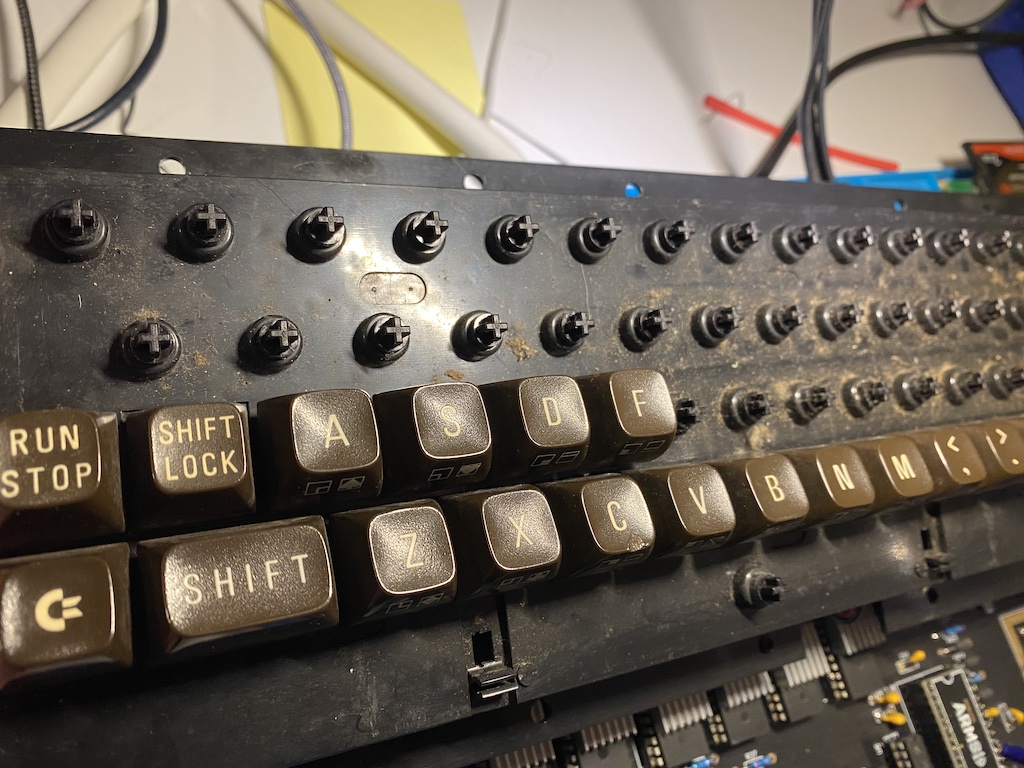
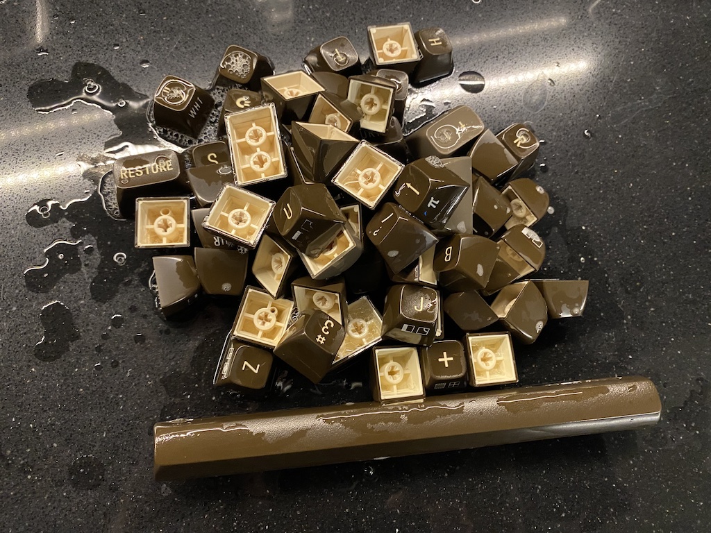
I washed the keys with soap and warm water and rinsed them a few times until all the dirt came off, and then I had them dried with a hair drier.
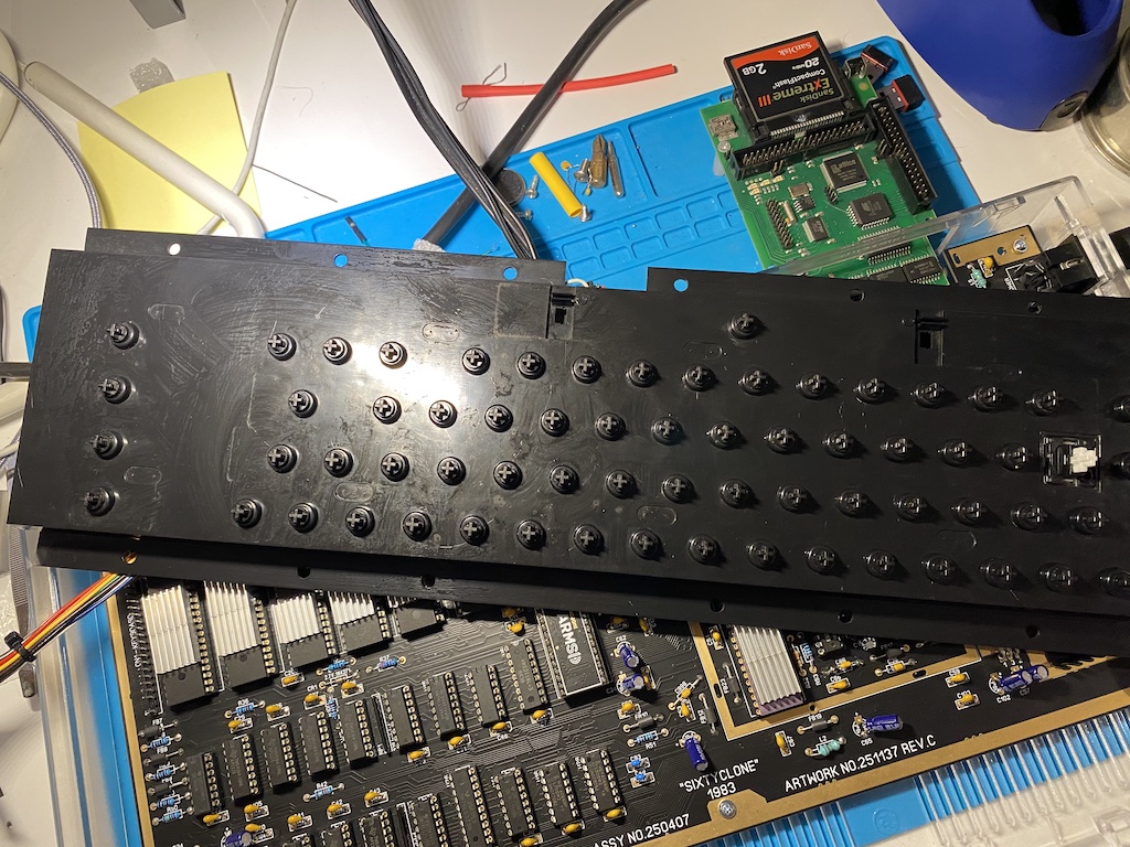
Then I cleaned the board.
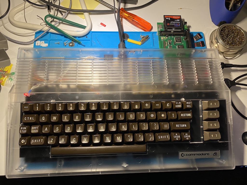
And then, I finally reassembled the keycaps into the keyboard. Here’s a layout picture to help you find all the key positions.
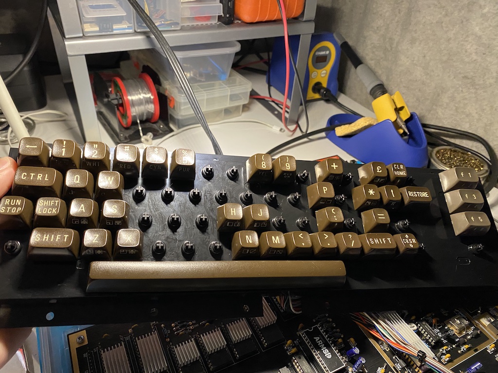
Nice and clean!
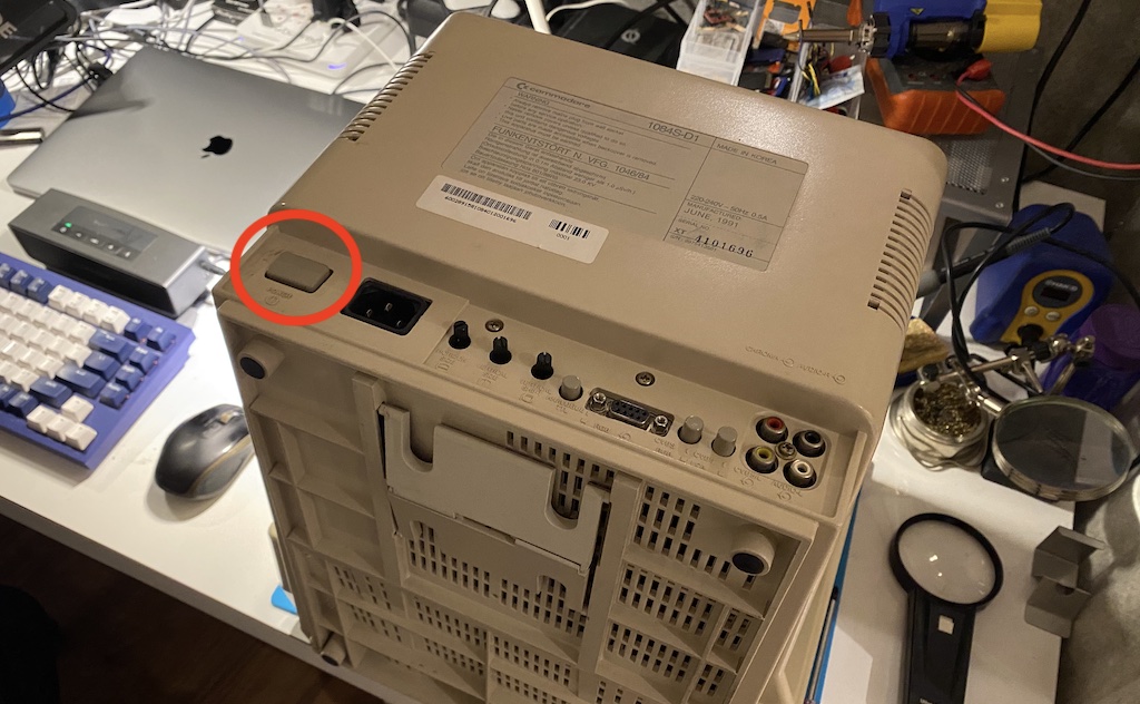
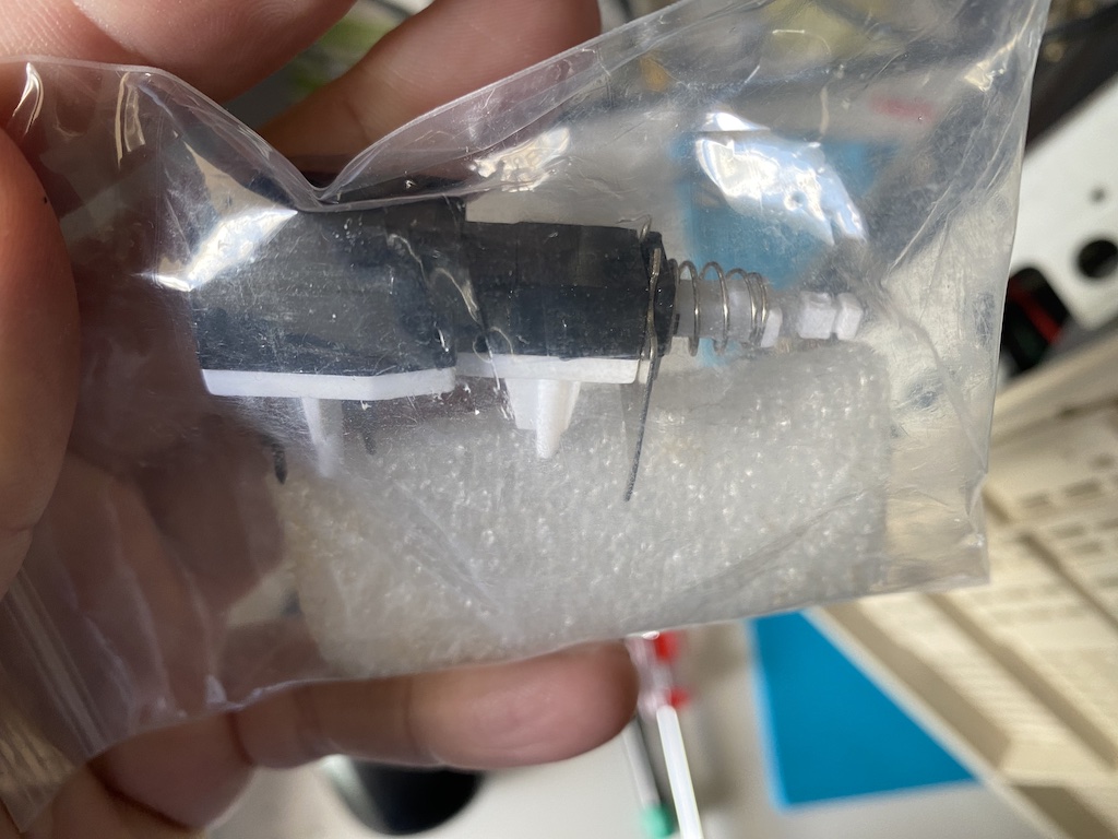
1084S power switch
One last thing. The Commodore 1084(S) and some Philips monitors used a special power switch that was famous for failing after some use. At some point in time, they would stop holding their position when clicked in for powering on. A bit of duct tape around the button would quickly solve the problem, but it’d still be annoying to use the mains cable to turn the monitor on and off.
Fortunately for me, this is a widespread issue; a few people are selling identical replacement switches online. I also have a good desoldering gun now, so it’s time to fix this problem once and for all.
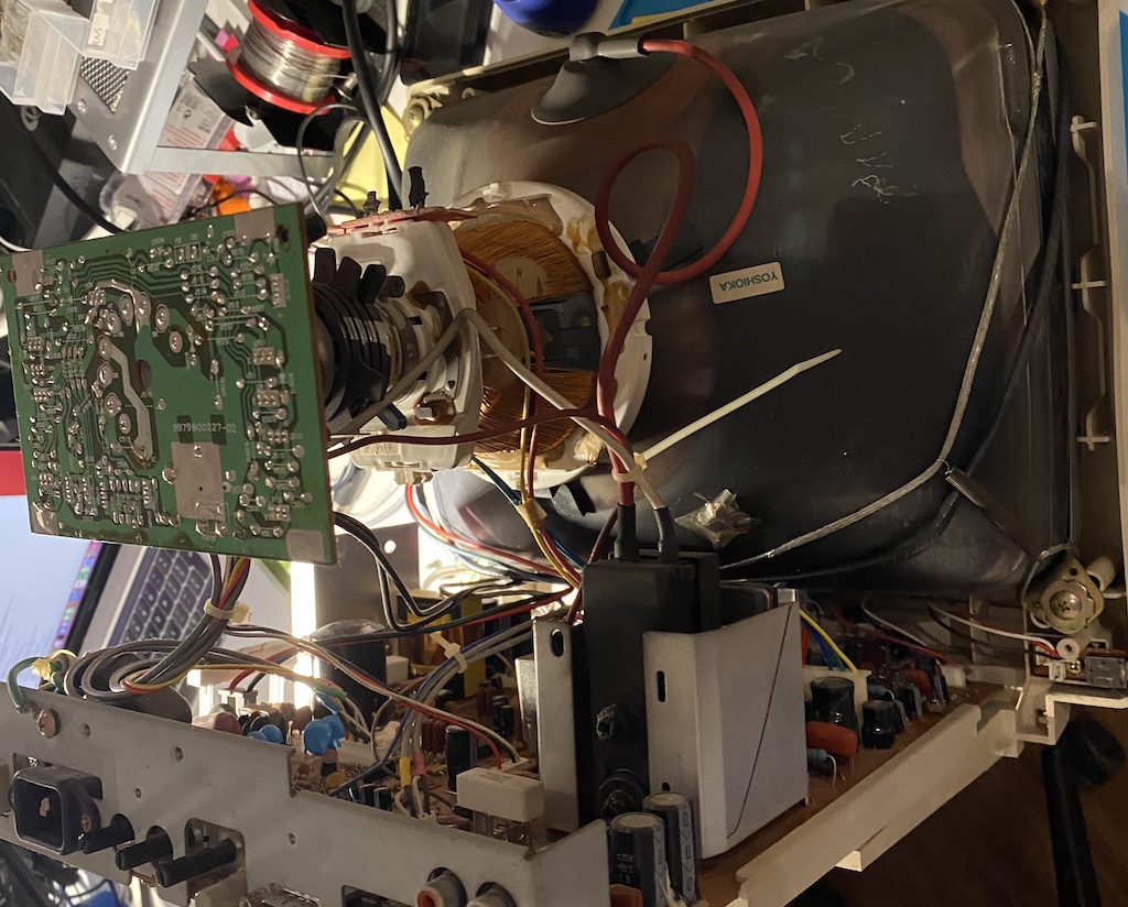
Disclaimer: CRTs can hold thousands of volts in their flyback circuits. If you don’t know how to discharge the tube or what you’re doing in general, you should not even take the plastic cover off. A CRT that has been powered off for an extended period won’t be safe either, as it builds static over time. Also, there are high-voltage capacitors in the electronics that, depending on whether there are bleeding circuits, can hold energy for a long time.
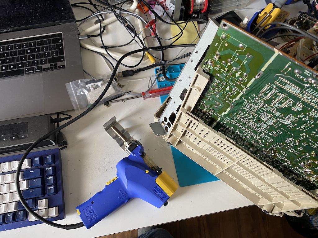
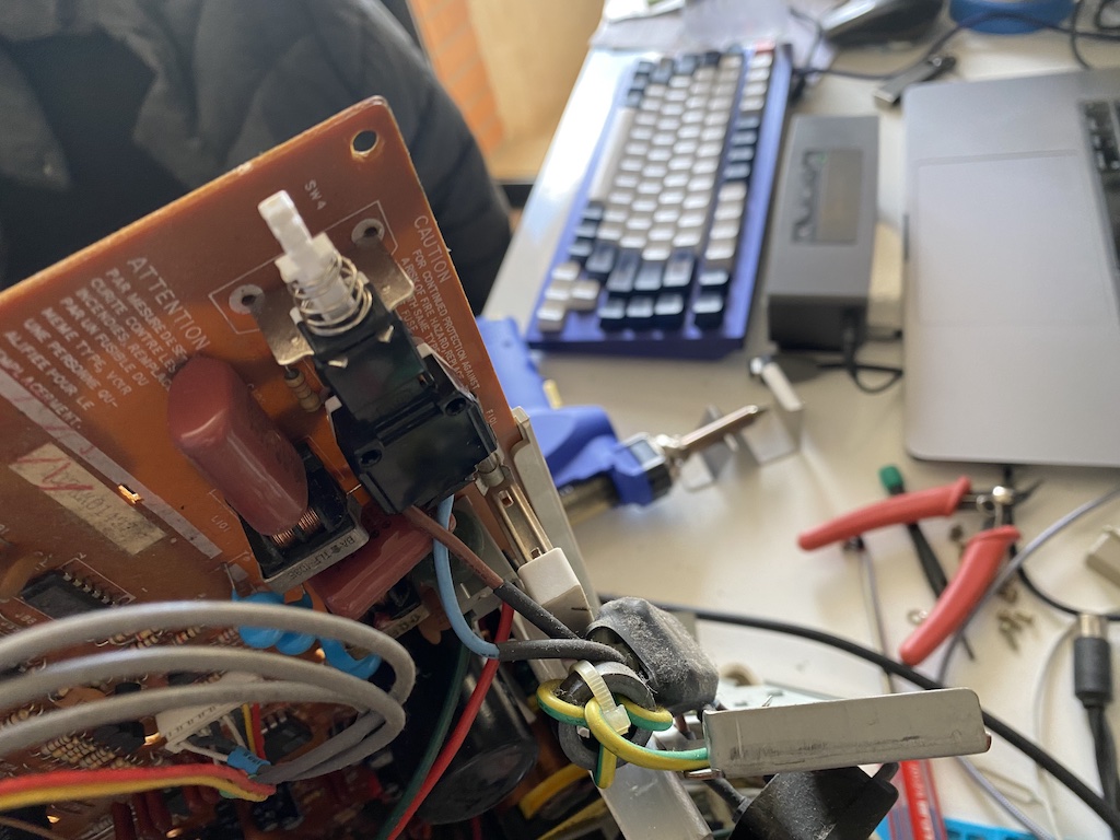
I removed the back steel panel that holds the external video and power connectors and then desoldered the power switch.
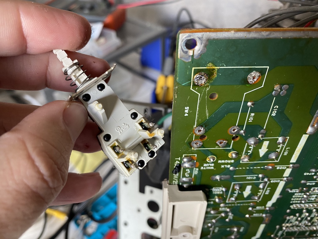
Tested the new switch with the multimeter to ensure it was working and soldered it back on the PCB.
Looks good to me. I reassembled everything together and closed the case. The 1084S was working perfectly now; the problem was solved.
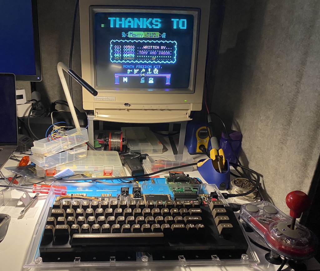
It’s done
This project is now complete. I plugged in my IDE64 adaptor and loaded a few games, and they all ran flawlessly. The SIDARM sounds excellent too, I can’t tell the difference from an original SID chip. The C64 looks beautiful and works perfectly.
Monty On The Run, of course. It has one of the best C64 soundtracks, the one that made Rob Hubbard famous (though some will say that the Commando soundtrack is his masterpiece).
One minor final detail: I had to buy a rectangular LED for this new C64C case (the breadbin case uses a round LED).
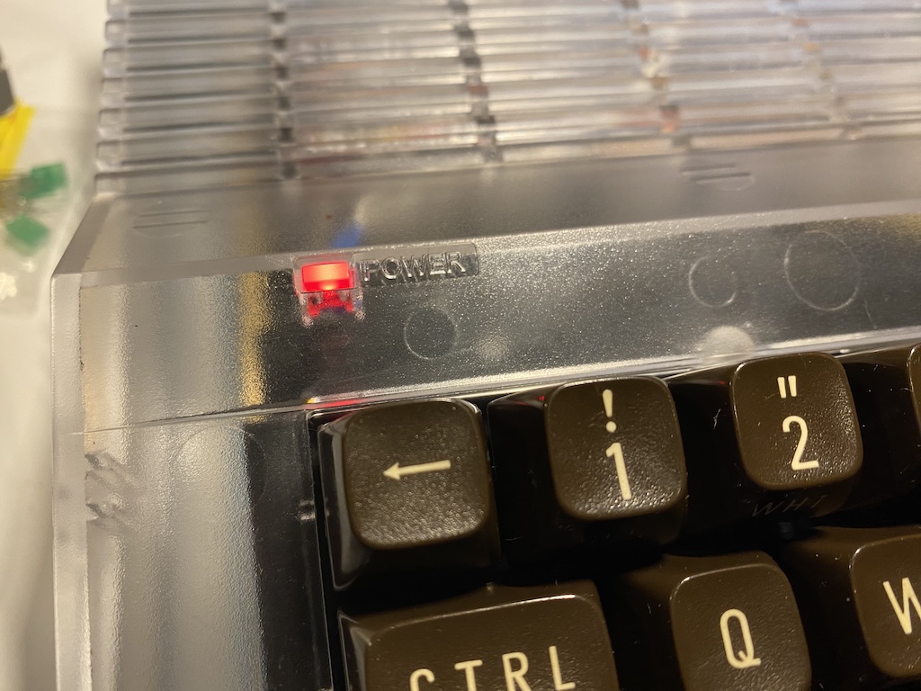
And here it is, fully assembled, final work.
❤️
Final words and future enhancements
I hope you enjoyed this write-up; this was one of the most fun and educational projects I ever did. I tried to include as much information and as many links as possible in the hope this will inspire others to do it too, which I definitely recommend. You might also be interested in my “Writing a C64 Asssembly Demo” blog.
This was not about owning a working Commodore C64; you can buy one off eBay if that’s what you want, and it will come off much cheaper than what this project cost me. Frankenstein 64 was about building one from scratch, going through all the hurdles, learning how everything works, solving the problems and having fun.
I still want to make a few enhancements to this machine at some point in the future. One of them is inspired by this video from Adrian Black: a kernal switcher using an EPROM and Arduino and making use of keyboard combinations.